Home

Détroit de Béring méditation réfugiés diode 0.6 v Supériorité Sans précédent Classer

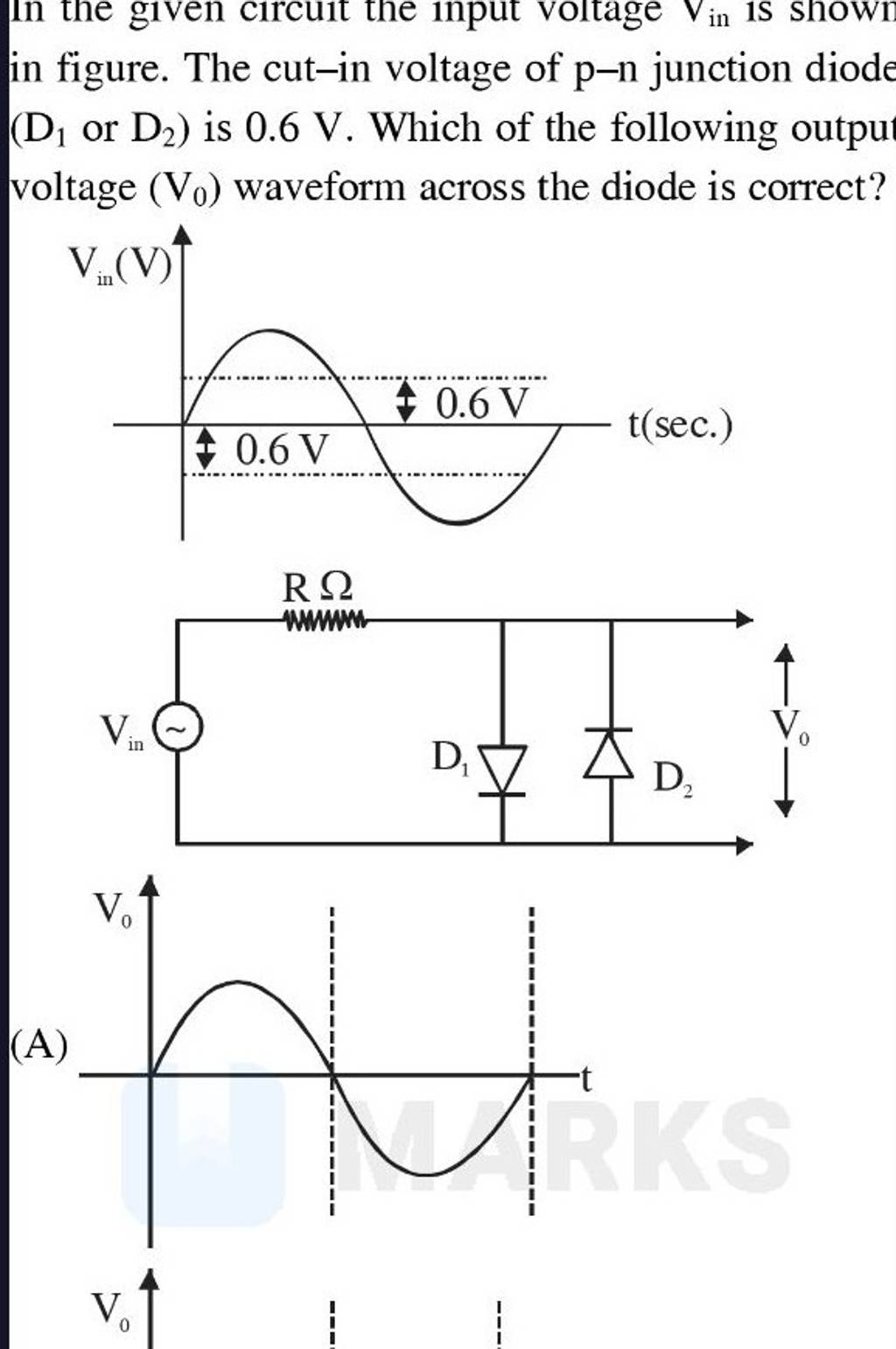
in figure. The cut-in voltage of p−n junction diode (D D1​ or D2​ ) is 0...

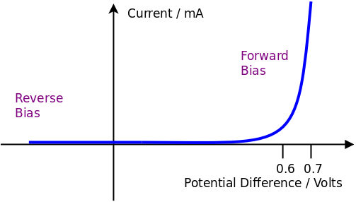
Shockley diode equation - Wikipedia

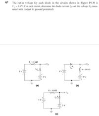
Answered: Q7 The cut-in voltage for each diode in… | bartleby

Solved] The diode cut-in voltage is 0.6 and the voltage drop acros

10 pcs Schottky Diode SR540 5A 40V Vd=0.6V@5A RoHS | eBay

SOLVED: 2) In the circuit shown below, by using the constant voltage drop  model with a diode drop 0.6V, determine Vo when VI = 5V. Note that you are  required to start
SOLVED: 2) In the circuit shown below, by using the constant voltage drop model with a diode drop 0.6V, determine Vo when VI = 5V. Note that you are required to start

4.19 A diode for which the forward voltage drop is 0.7 V at 1.0 mA is  operated at 0.5 V.What is the - YouTube
4.19 A diode for which the forward voltage drop is 0.7 V at 1.0 mA is operated at 0.5 V.What is the - YouTube

Solved] The diode used in the circuit has a fixed voltage drop of 0.

For the circuit shown below each diode has Vr = 0.6 V and

Solved Consider the diode circuit shown in Fig. 5 and by | Chegg.com

The cutin voltage for each diode shown below Vγ = 0.6 V.

Diodes
Diodes

Solved) - 5. A forward bias of 0.6 V is applied to a Si pn diode.  Calculate... (1 Answer) | Transtutors
Solved) - 5. A forward bias of 0.6 V is applied to a Si pn diode. Calculate... (1 Answer) | Transtutors

I(V) curves of a TD diode prepared by the 1-step process on p-type Cz... |  Download Scientific Diagram
I(V) curves of a TD diode prepared by the 1-step process on p-type Cz... | Download Scientific Diagram

Solved Assume V,-0.6 V for all diodes, and assume the zener | Chegg.com

Chapter 3 Diode Circuits - ppt download

Ge and Si diodes start conducting at 0.3 V and 0.7 V respectively. In the  following figure if Ge diode connection are reversed, the value of Vo  changes by : (assume that
Ge and Si diodes start conducting at 0.3 V and 0.7 V respectively. In the following figure if Ge diode connection are reversed, the value of Vo changes by : (assume that

In the given circuit the input voltage Vin is shown in figure. The cut-in  voltage of p-n junction diode (D1 or D2) is 0.6 V. - Sarthaks eConnect |  Largest Online Education Community
In the given circuit the input voltage Vin is shown in figure. The cut-in voltage of p-n junction diode (D1 or D2) is 0.6 V. - Sarthaks eConnect | Largest Online Education Community
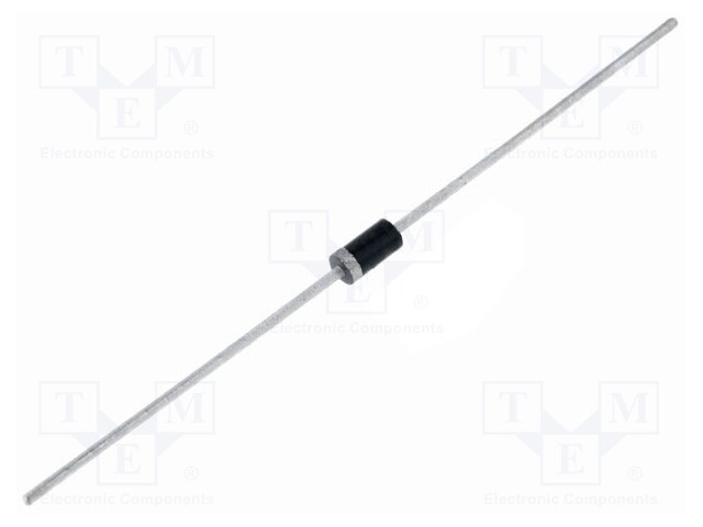
1N5819 YANGJIE TECHNOLOGY - Diode: Schottky rectifying | THT; 40V; 1A;  DO41; tape; Ufmax: 0.6V; 1N5819-YAN | TME - Electronic components
1N5819 YANGJIE TECHNOLOGY - Diode: Schottky rectifying | THT; 40V; 1A; DO41; tape; Ufmax: 0.6V; 1N5819-YAN | TME - Electronic components

SOLVED: The diode as shown in Figure 5 is a silicon diode with turn-on  offset voltage of 0.6V 1 k9 Vi 2 k Figure 5 (a) Find the voltage V: by  applying
SOLVED: The diode as shown in Figure 5 is a silicon diode with turn-on offset voltage of 0.6V 1 k9 Vi 2 k Figure 5 (a) Find the voltage V: by applying

Tut01S.pdf - HET287 Tutorial 1 Solutions 1. Consider the circuit shown in  Figure 1. Determine the diode current ID and diode voltage VD for a Vγ = 0.6  | Course Hero
Tut01S.pdf - HET287 Tutorial 1 Solutions 1. Consider the circuit shown in Figure 1. Determine the diode current ID and diode voltage VD for a Vγ = 0.6 | Course Hero

The cutin voltage for each diode in figure is Vγ = 0.6 V. Each diode  current is 0.5 mA. The value of R1 R2and R3 will be respectivelya)10  kΩ, 5 kΩ, 2.93
The cutin voltage for each diode in figure is Vγ = 0.6 V. Each diode current is 0.5 mA. The value of R1 R2and R3 will be respectivelya)10 kΩ, 5 kΩ, 2.93